Breadboard Video Card
Introduction
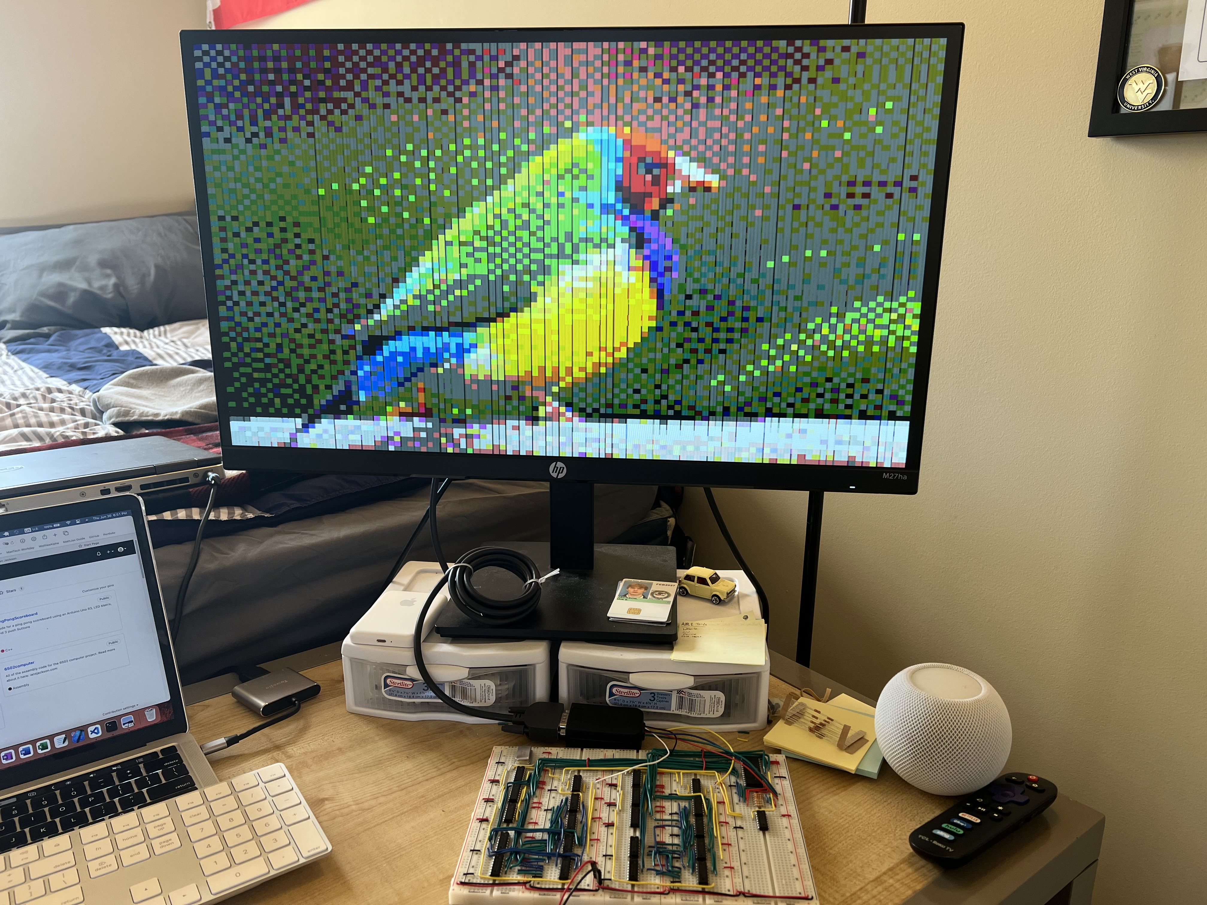
The goal of this project is to make a video card on a breadboard. Most of the ICs used in this project are binary counters and NAND gates. The resolution of the breadboard is not the most impressive, but it is a working video card using ICs. The resolution it outputs to the monitor via a VGA cable is 800x600 pixels, but what displayed is a 100x75 pixel image. It supports 64 colors and runs at 10 MHz. The image data is read from an EEPROM.
All of the parts of the project and information was sourced from Ben Eater. I strongly encourage you check out his website at eater.net.
How It Works
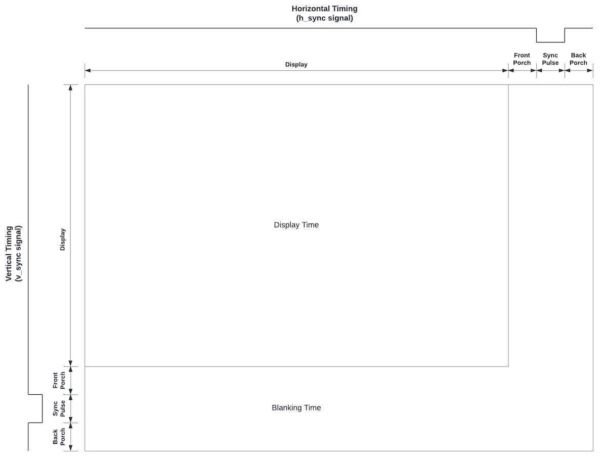
The way monitors display information on a screen is like how CRT monitors work. Instead of an electron beam moving across the screen, the monitor paints a color at each pixel across the screen then moves down to the next line. The first step to creating a video card is determining what resolution the video card will run at.
Using the timing information for a VGA signal, it is easiest to "trick" the monitor into thinking it is in 800x600 resolution. The timing on the VGA website for this resolution is based on a 40 MHz pixel clock. I have a 10 MHz clock, so the amount of pixels in the scanning part of the horizontal scan can be divided by 4 and all of the timing still works out. So in reality, the resolution of the image is 200x600 px. The timing of each scanline part can be seen in the table below.
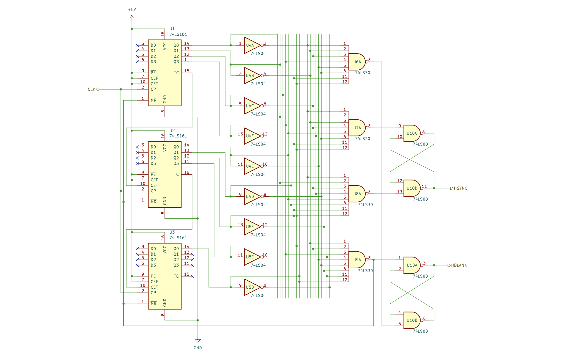
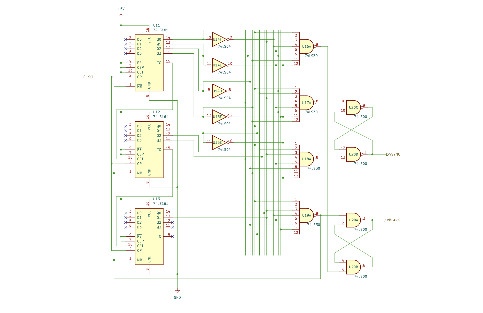
Binary counters and logic gates are used to determine what part of the scanline the monitor is in, or when the monitor needs to display pixel data and when not to. The circuit diagram for the horizontal timing and vertical timing circuits is seen in the images below.
Timing Tables
Horizontal Timing
| Scanline Part | Pixels | Time [μs] |
|---|---|---|
| Visible Area | 200 | 20 |
| Front Porch | 10 | 1 |
| Sync Pulse | 32 | 3.2 |
| Back Porch | 22 | 2.2 |
| Whole Line | 264 | 26.4 |
Vertical Timing
| Scanline Part | Lines | Time [μs] |
|---|---|---|
| Visible Area | 600 | 15.84 |
| Front Porch | 1 | 0.0264 |
| Sync Pulse | 4 | 0.1056 |
| Back Porch | 23 | 0.6072 |
| Whole Line | 628 | 16.5792 |
Displaying Images in 64 Colors
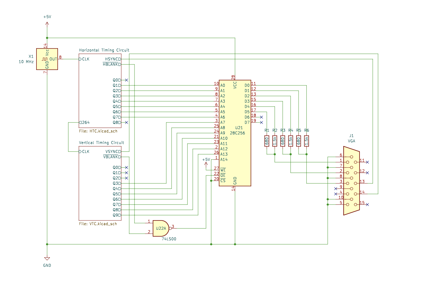
Now that the video card can determine whether to display a pixel or not and where it is on the screen, it now just needs an image to display. The image data is stored on an EEPROM, the AT28C256 (the same one used on the 6502 computer. The horizontal and vertical position are used to address the image data in the EEPROM.
Since the EEPROM only has 15 address lines, the image resolution has to be cut down. The most and least significant bit of the horizontal counter were dropped and the 3 least significant bits of the vertical counter were dropped. This cuts the final resolution of the image to be 100x75 pixels. The EEPROM can only output data when it is in the display intervals, so the inverted blanking outputs of the vertical and horizontal counters are NANDed to the chip enable (CE) input.
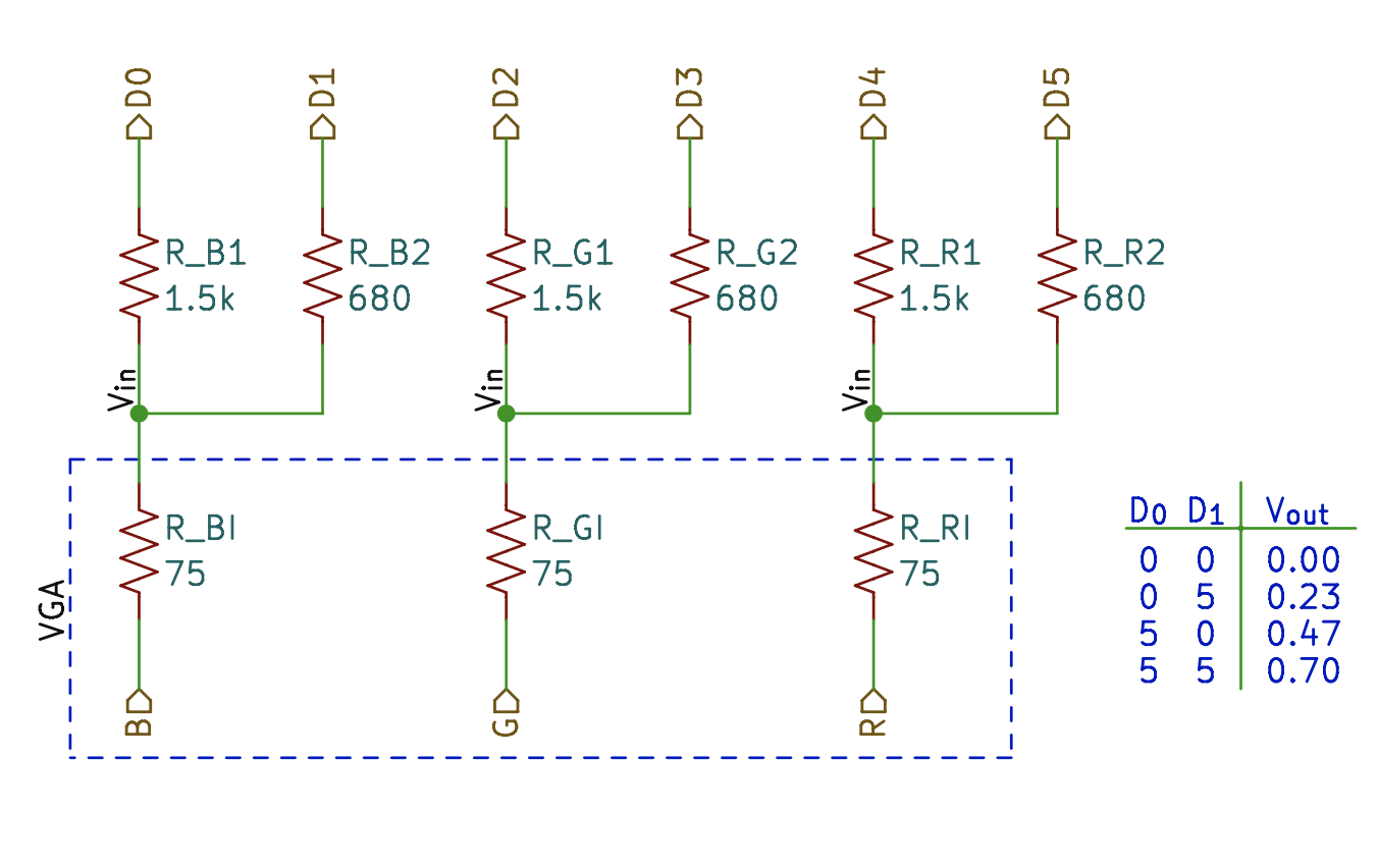
The RGB pins on the VGA allow a maximum voltage of 0.7V with 75Ω of resistance. A voltage divider can be implemented such that the maximum voltage into the VGA is 0.7V and minimum into the VGA is 0V, with two voltages in between. This means that there are 64 different combinations of input voltages into the VGA, thus 64 colors.
Diagrams & Pictures
Future Work
- Integrate with the W65C02S computer project so image data can be read from RAM.
- Design a higher quality video card.
- Look into a designing a PCB for this project.
