W65C02S Computer
Introduction
The goal of this project was to create an 8-bit computer centered around the W65C02S microprocessor. The 6502 microprocessor uses CMOS technology and provides 16 addressing pins, 8 data pins, 70 instructions, and more. The 6502 is far outdated, it was released in 1983. Some of the notable uses of the 6502 microprocessor are the Apple IIc and the Atari Lynx.
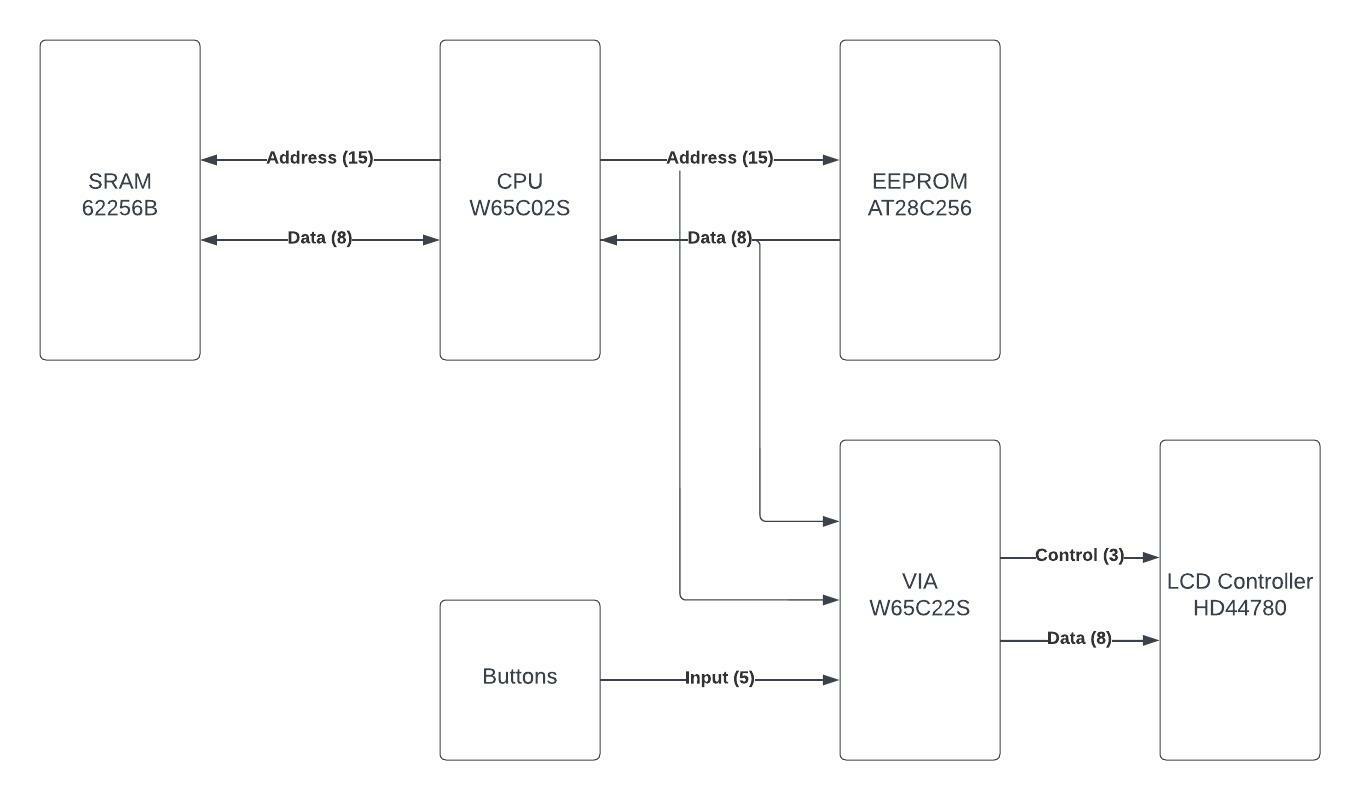
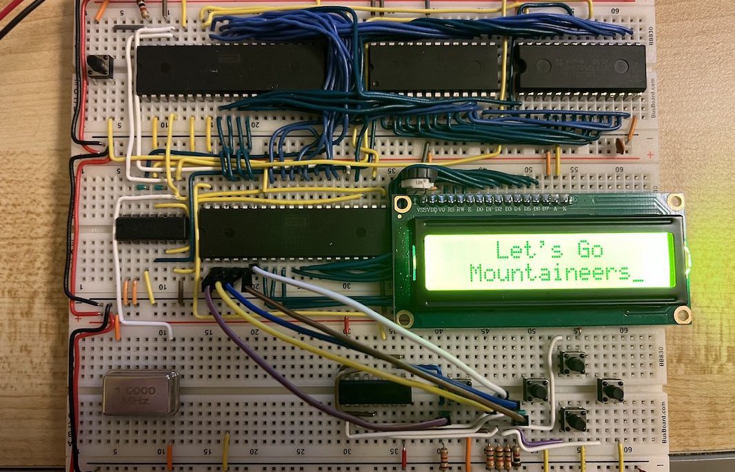
The computer is equipped with the AT28C256 EEPROM, 62256B SRAM, W65C22S versatile interface adapter, and the HD44780 LCD controller. The first goal of project was to print information on the dot matrix LCD screen. After finishing this goal, the new goal is to take advantage of the hardware interrupts to add I/O to computer.
All of the parts of the project and information was sourced from Ben Eater. I strongly encourage you check out his website at eater.net.
Hardware Description
As mentioned above, the 6502 is a CMOS 8-bit microprocessor. The processor has an 8-bit data bus, 16-bit address bus, 8-bit ALU, 16-bit program counter, and support for interrupts. The 6502 markets itself as a low-power chip great for SoC designs.
The data sheet can be found here.
The AT28C256 is a CMOS 256 Kb electronically erasable programmable ROM (EEPROM). Since the data of this computer is 8-bits, the EEPROM can store 32 KB of memory. The EEPROM for this computer is home to all of the instructions. To program the EEPROM, the TL866 II Plus EEPROM Programmer was used.
The data sheet can be found here.
The 62256B is a CMOS static RAM (SRAM) device. Like the AT28C256, the SRAM can store 256 Kb or 32 KB of information. The primary use of the SRAM on this computer is to house the stack, so subroutines could be used in the code.
The data sheet can be found here.
The W65C22S is a versatile interface adapter (VIA) that allows the control of I/O. The VIA features two 8-bit peripheral ports that are bidirectional and 16 registers to interface with. The W65C22S is mainly used with other microprocessors in the 65xx family. Port B and 3-bits of port A are used for controlling with the LCD screen. The remaining 5-bits of port A is used for button input.
The data sheet can be found here.
The HD44780 is a dot matrix LCD controller that can be configured for many purposes. The controller is configured to be in 8-bit mode, 2-line display, and 5x8 font. All of these configurations are communicated through the VIA.
The data sheet can be found here.
Code Description
The programs for the 6502 computer are written in x86 Assembly. All of the different instructions are found in the 6502 data sheet. Once the program is finished, it is loaded onto the EEPROM using the VASM assembler. All of the different programs used for the 6502 can he found here.
Debugging
Like any project, it is inevitable to run into a bug. To help find the issue the address lines, data lines, read/write bit, and clock are hooked up to an Arduino Mega. The Arduino reads the inputs and outputs that to the serial monitor.
How It Works
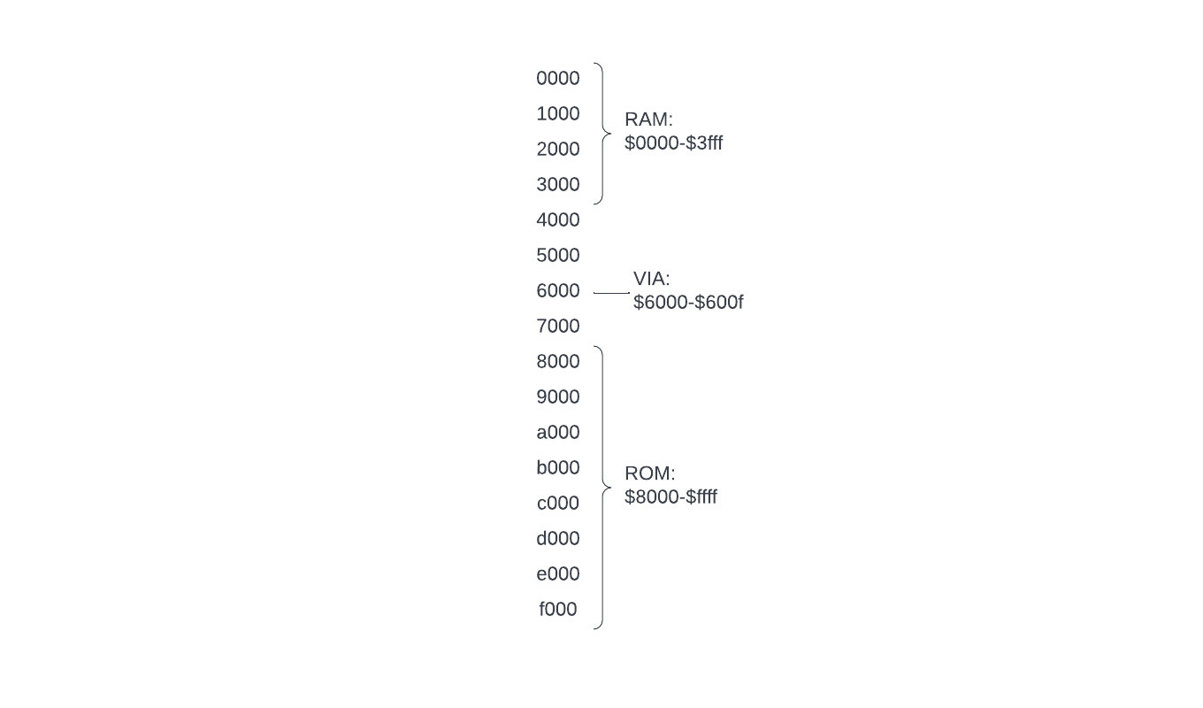
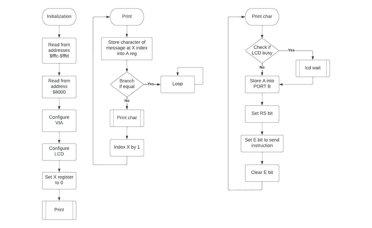
The computer is reset using the RESB pin (active low), it then goes through a reset sequence lasting seven clock cycles. The computer is then initialized at addresses $fffc-$fffd. The code then directs the CPU to address $8000, which is the location of the start of the code on the EEPROM. Note that the code is stored on the EEPROM at address $0000, but to the CPU that is address $8000. This is because the CPU has 16 address lines, but the EEPROM has only 15 address lines. Using some combinational logic, the EEPROM is enabled when the CPU is looking for an address between $8000-$ffff. The dedication of addresses can be seen in the diagram below.
Once the computer is initialized, it starts fetching instructions from the EEPROM through the data line. The first instructions include sending bytes of data to the VIA to configure the LCD controller and the VIA: setting the data direction of port B to output and the three most significant bits of port A to output. The addresses dedicated to communicating to the VIA are $6000-$600f, since the VIA has 16 registers to interface with.
When the program outputs text to the LCD, it does so at one character at a time. To make the code more efficient, subroutines are used. Subroutines are possible only with the SRAM. The addresses dedicated to the SRAM are $0000-$3fff. When the subroutine is called, the CPU stores the address it was last at on the SRAM stack. The CPU then runs though each character, printing it on the display.


